|
|
|
Introduction Phase
Contrast Microscopy (PCM) Phase
Contrast Microscopy (PCM)
The easiest and most common way to image biological samples is using
phase contrast, which is a special contrast-enhancing imaging method for
transmitted-light microscopes invented by Frits Zernike (1888-1966) in
1932 [1] and introduced into microscopic practice by
August Köhler (1866-1948) and Loos in 1941 [2,
3].
Soon it revolutionized biological and medical research and earned its inventor
the Nobel Prize in Physics in 1953.
Amplitude and Phase Objects
|
 |
|
|
|
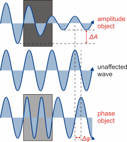
Illustration of the different impact of amplitude and
phase objects on transmitted light. (Figure taken from diploma thesis of
Steve Pawlizak, 2009.) |
|
|
Using an ordinary (bright-field) transmitted-light microscope, the produced
images of very thin and transparent objects, like living cells or biological
tissues, usually suffer from lacking contrast, which makes it very difficult
and in many cases even impossible to recognize and distinguish delicate
sample structures or image details. This is because light absorption of
such objects is too low to provide sufficient amplitude changes of the
transmitted light (bright-dark-contrast). However, individual sample structures
(e.g. cell nucleus, cytoplasm, organelles) show little density differences,
leading to small differences of the refractive indices and, for this reason,
to different optical path lengths. If light waves pass those structures,
they experience a certain phase shift that corresponds to the respective
optical path lengths. The phase contrast technique is intended to convert
such phase shifts into amplitude differences that are detectable by the
human eye (bright-dark-contrasts).
Principle
When light passes through an object that is more optically dense than
its environment (background), the wavefronts are retarded with respect
to the unaffected, bypassing background light.
It may be assumed that the phase shift of the so-called object
light is ≤ 90° (corresponding to an optical path difference
of ?/4), as it is the case for most biological samples. The idea
behind visualization of phase shifts in the object light is to change the
phase of the background light in such a manner that background and object
light weaken or even cancel each other out when interfering in the primary
image plane. Consequently, the object would appear dark against the background.
|
|
 |
|
|
|
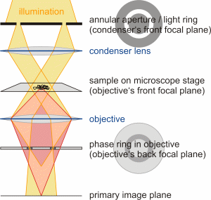
Schematic simplified assembly of a phase contrast microscope
containing an annular aperture (light ring) in the
condenser and an accordant phase ring in the objective. The background
light is colored orange and the object light is rose. (Figure taken from
diploma thesis of Steve Pawlizak, 2009.) |
|
|
|
In order to do that, the background light must be influenced without affecting
object light (which is already phase shifted due to the object). This is
achieved by placing a annular aperture
(light ring) in the front focal plane of the condenser and a matching phase
ring in the back focal plane of the objective (see figure on the
left). Due to this alignment, the parallel light fronts leaving the annular
aperture are focused by the objective directly onto the phase ring, i.e.
nearly all background light has to pass through the phase ring, which serves
in two ways: On the one hand, the phase ring reduces the intensity of the
background light by 70 to 90% like a neutral density filter and, on the
other hand, it adds a constant phase shift of 90° (?/4) like
a quarter-wave plate. The reduction of the amplitude is necessary, because
the object light is much less intense than the bright direct light.
If an object is placed in the light path, the object light gets deflected,
only slightly passing through the phase ring. Most object light passes
by and remains unaffected as desired. Recombining the background and object
light in the primary image plane results in an effective phase shift of
about 180° (?/2), which means destructive interference. In fact,
for best contrast, both phase shifts should complement one another as well
as possible to 180°. For this reason, the properties of the phase ring
must take into account the most frequent refractive index and the thickness
of the samples.
Starting at a certain thickness, phase contrast objects show light
or dark "halos" along their edges and simulate a kind of 3D effect. This
is due to the fact that a small part of the diffracted object light passes
through the phase ring as well and interferes at the image plane. Thus,
these halos may not necessarily represent the actual structure of the sample.
(This article is taken from the diploma thesis of Steve
Pawlizak, University of Leipzig, 2009.)
References:
|
|
|
F. Zernike: Das Phasenkontrastverfahren
bei der mikroskopischen Beobachtung, Zeitschrift für technische
Physik 16:454-457 (1935) |
|
|
|
|
|
|
A. Köhler, W. Loos: Das Phasenkontrastverfahren
und seine Anwendungen in der Mikroskopie, Die Naturwissenschaften
29:49-61 (1941) |
|
|
|
|
|
|
W. Loos: Das Phasenkontrastverfahren nach
Zernike als biologisches Forschungsmittel, Klinische Wochenschrift
(Journal of Molecular Medicine) 20(34):849-853 (1941) |
|
|
|
|
|
|
A. Köhler: Ein neues Beleuchtungsverfahren
für mikrophotographische Zwecke, Zeitschrift für wissenschaftliche
Mikroskopie und mikroskopische Technik 10:433-440 (1893) |
|
|